Results obtained
It has been found that it is possible to utilize a cross-flow one-pass heat exchanger, to produce a qualitative evaluation of the flow pattern. In this concept, inlet and outlet temperature of the working fluid are used to make a judgement on the intensity of the surrounding external flow. This is believed to be possible, based on thorough theoretical research and experimental study. Even though the concept of utilising heat transfer rate as an indication of the mass-flow intensity has been proven to some extent, it is yet to be ready for implementation in a real life system. This refers to mechanical workflow being in a scientific phase of the development.
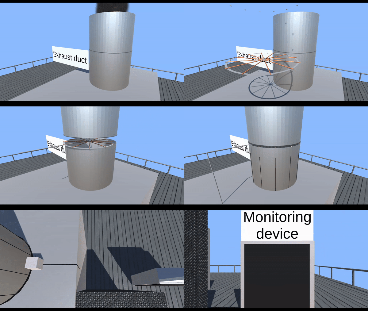
To emulate the CFD image to a sufficient level, the software team has used twelve pipes with one sensor each. The latter is located on the outside of the exhaust duct. The pipes are placed in the cross section, to map and visualize the flow.
To collect the data from sensors the electrical domain has put together three electrical systems. To gather all the data from the sensors, there have been put together a couple of solutions. The solutions are made of PLC systems and a microcontroller. The PLC system is built from Siemens modules, and designed to collect thermocouple signals.
The Arduino PCB module is using thermocouple amplifiers to make a thermocouple input board, that can be used in all temperature sensing systems. It can collect data from thirteen thermocouples, and still utilize all ports on the Arduino.
System concept of operation

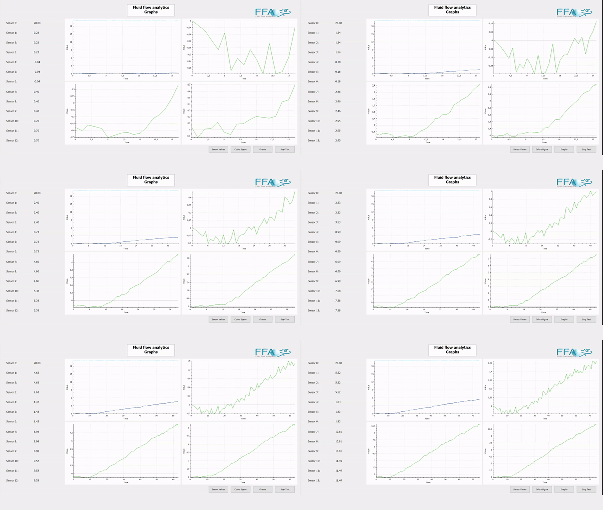
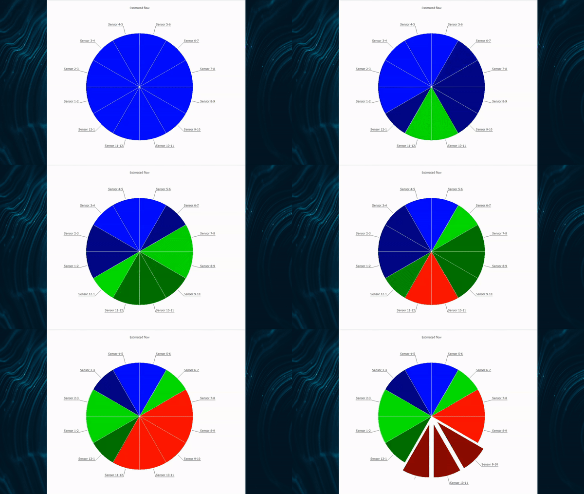
Raw signal visualization and Estimated flow visualization


